
Call us now :08045803488
 Send Inquiry
 Send Inquiry
Gear Flow Dividers FD5000 5100 Series
Price 69000.00 INR/ Piece
MOQ : 1 Piece
Gear Flow Dividers FD5000 5100 Series Specification
- Valve Type
- Flow Divider Valve
- Features
- Accurate flow division, Low leakage, No slip-stick effect, Compact design
- Material
- High strength cast iron
- Control System
- Manual or hydraulic control
- Connection Type
- Threaded ports
- Valve Size
- FD5000/5100 series: Multiple sizes available
- Structure
- Modular gear flow divider
- Application
- Hydraulic systems, synchronizing two or more cylinders
- Voltage
- N/A (hydraulic operation)
- Sealing
- High performance NBR seals
- Type
- Gear Flow Divider
- Power
- Hydraulic
- Pressure
- Up to 210 bar (3000 psi)
- Media
- Hydraulic oil
- Port Size
- 3/8 inch to 1 inch
- Temperature
- -20C to 80C
- Number of Sections
- 2, 3, or 4 sections available depending on model
- Surface Treatment
- Anti-corrosive painting
- Compatibility
- Suitable for mineral oil and synthetic hydraulic fluids
- Maintenance
- Low maintenance design
- Weight
- Depends on size (approx. 4 kg to 12 kg)
- Mounting
- Bolt-on / flange
- Flow Rate Range
- 8 LPM to 120 LPM
- Flow Division Accuracy
- 1.5% between sections
Gear Flow Dividers FD5000 5100 Series Trade Information
- Minimum Order Quantity
- 1 Piece
- Payment Terms
- Cash on Delivery (COD), Letter of Credit (L/C), Paypal, Western Union, Cash Against Delivery (CAD), Telegraphic Transfer (T/T), Delivery Point (DP), Days after Acceptance (DA), Cash in Advance (CID), Cheque, Cash Advance (CA)
- Supply Ability
- 100 Pieces Per Day
- Delivery Time
- 7-30 Days
- Sample Available
- Yes
- Sample Policy
- Sample costs shipping and taxes has to be paid by the buyer
- Main Export Market(s)
- Australia, Central America, North America, South America, Eastern Europe, Western Europe, Middle East, Africa, Asia
- Main Domestic Market
- All India
Gear Flow Dividers FD5000 5100 Series About
Gear Flow Dividers FD5000 5100 Series
| Displacement cc/rev: | 21 - 115.9 |
| Gear Widths: | 1/2" - 2.3/4" |
| Max PSI / BAR: | 2500 / 172 |
| RPM: | 400 - 2000 |
Free Technical Downloads
FD5000 5100 Data Sheet
FD5000 5100 Codebook
FD5000 / 5100 Function
The main function of the PERMCO FD5000 / 5100 Flow Divider, is to accept flow then divide it equally or unequally. Alternatively it can combine flow in the return direction and distribute pressure based on your requirements.
The main benefits of using a PERMCO flow divider in your hydraulic system is to:
- Simplify circuitry.
- Increase life of components.
The above will achieve a reduction in costs.
Basic Sizing Requirements
The most efficient gear widths are 1 or larger.
The most efficient speed of the PERMCO flow dividers is between 700 -1400 RPM.
Units with ALL gear widths of 1/2 and 3/4 should be avoided.
EXAMPLES: Units with 1/2 gears would work best with another section of a least 1-1/2
Units with 3/4gears would work best with another section of a least 1-1/4
In three section units or larger, it is good practice to position the inlet port nearest the largest gear section. It is also recommended that the largest gear section be placed in the centre of the unit.
For applications where speeds are below 500 RPM or above 1400 RPM, and/or where pressure across the unit may exceed 2000 PSI (138 Bar) for the 5000 series / 2500 PSI (172 BAR) for the 5100 series, please CONTACT US to discuss further.
How to Select Your Flow Divider
To select your PERMCO flow divider, this procedure should be followed:
For equal flow division:
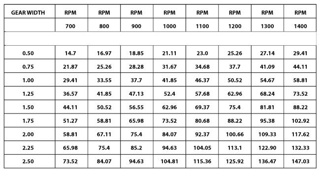
Select a gear width greater than one (1) inch from the charts keeping the speed between about 700 RPM and 1400 RPM.
For unequal flow division use the following procedure:
- Determine the outlet flow required for each leg of the hydraulic circuit.
- Use charts below to select a series and gear width for the leg with the greatest flow (keeping gear widths greater than one (1) inch).
- Move straight up the chart to select the other gear widths by choosing gear widths with the closest flow at the same RPM.
- Check the actual flow for each section to determine if acceptable using the following formula.
GEAR WIDTH / (TOTAL GEAR WIDTH) X TOTAL
FLOW =FLOW FOR SECTION - If the flows are not acceptable, repeat from step (2) by choosing a different gear width or moving to a chart in another series.
FD5000 / 5100 Flow Chart
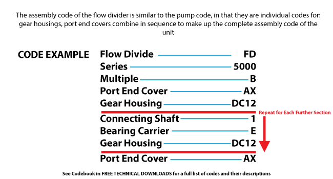
Flow Divider Assembly Coding Example
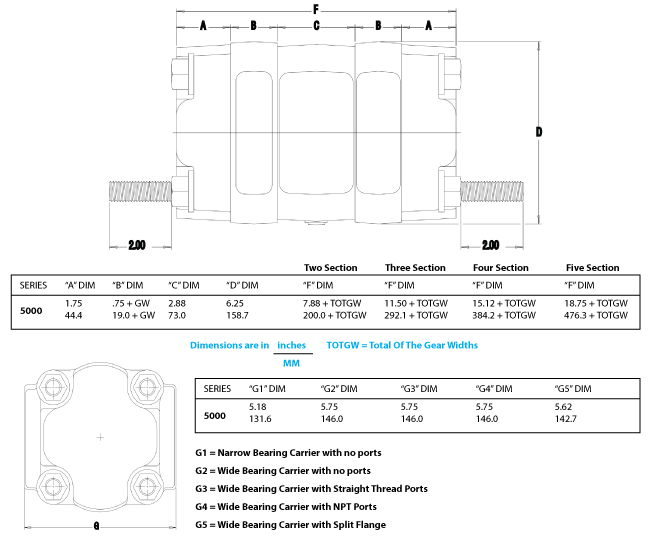
FD5000 / 5100 Dimensions
Accurate Synchronization for Hydraulic Systems
The FD5000/5100 Gear Flow Dividers are engineered to split hydraulic flow with remarkable accuracy, ensuring synchronized operation of two or more actuators. Their modular construction and low-slip design make them ideal for applications where precision and repeatability are crucial. Compact yet powerful, these dividers support hydraulic systems across industries, offering adaptability for various configurations.
Rugged Construction and Flexible Mounting
Built with high-strength cast iron and treated with durable anti-corrosive paint, these flow dividers deliver long-term reliability in tough environments. Designed for both bolt-on and flange mounting, they integrate easily into new or existing systems. Available in multiple port sizes and scalable sections, they accommodate a wide range of hydraulic requirements.
FAQ's of Gear Flow Dividers FD5000 5100 Series:
Q: How do the FD5000/5100 Series Gear Flow Dividers maintain flow division accuracy?
A: The FD5000/5100 series uses precision-engineered modular gears to split the hydraulic flow evenly between sections, maintaining a high division accuracy of 1.5%. This ensures reliable synchronization between connected hydraulic cylinders or actuators, minimizing operational errors.Q: What types of hydraulic fluids are compatible with these flow dividers?
A: These gear flow dividers are compatible with both mineral oil and synthetic hydraulic fluids, making them versatile for a broad spectrum of hydraulic applications.Q: When should I choose a 2, 3, or 4-section model?
A: The number of sections should be selected based on the number of hydraulic actuators requiring synchronized operation. Choose 2, 3, or 4 sections to match the specific needs of your hydraulic circuit and application.Q: Where are the FD5000/5100 Series typically installed in hydraulic systems?
A: These flow dividers are designed for bolt-on or flange installation directly into hydraulic circuits, usually positioned between the pump and multiple actuators, where precise flow distribution is necessary.Q: What benefits do the FD5000/5100 Flow Dividers offer for hydraulic systems?
A: They provide accurate flow division, low leakage, a compact design, and reduce the risk of slip-stick effects. This results in improved reliability and consistent performance, especially in applications requiring synchronized movement.Q: How is maintenance managed for these gear flow dividers?
A: The FD5000/5100 series features a low-maintenance design, utilizing high-performance NBR seals and robust cast iron bodies. Regular inspection and occasional seal replacement are typically sufficient to keep the units operating efficiently.
Tell us about your requirement

Price:
Quantity
Select Unit
- 50
- 100
- 200
- 250
- 500
- 1000+
Additional detail
Mobile number
Email

More Products in Gear Flow Divider Category
Gear Flow Dividers FD3000 3100 Series
Price 69000.00 INR / Piece
Minimum Order Quantity : 1 Piece
Flow Rate : 20 LPM to 900 LPM
Material : Cast iron body, steel gears
Structure : Other
Pressure : High Pressure
Gear Flow Dividers FD7500 7600 Series
Price 69000.00 INR / Piece
Minimum Order Quantity : 1 Piece
Flow Rate : 20900 LPM
Material : Cast Iron
Structure : Other
Pressure : High Pressure
Gear Flow Dividers FD124 424 Series
Price 57000.00 INR / Piece
Minimum Order Quantity : 1 Piece
Flow Rate : Speeds of up to 3000 RPM
Material : Cast Iron
Structure : Other
Pressure : High Pressure

 Send Inquiry
Our Products
- Vane Pumps
- Piston Pumps
- Veljan Vane Motors
- Veljan Hydraulic Seat Valve
- Veljan Direction Control Valves
- Hydraulic Gear Pumps & Motors
- Veljan Check Valves
- Veljan Flow Control Valves
- Veljan Pressure Control Valves
- High Pressure Gear Motor
- Roller Bearing Gear Motor
- Gear Flow Divider
- High Pressure Gear Pump
- Roller Bearing Gear Pump
- Vane Pump Cartridge Kits
- Diverter Valves
- Pressure Control Valves
- Flow Control Valves
- Hydraulic Motors Accessories
- Hydraulic Pumps
- Hydraulic Seat Valves
- Mobile Sectional Valves
- Hydraulic Check Valves
- Hydraulic Flow and Proportional Control Valves


MZ-3, Bansi Trade Centre, 581/5, M. G. Road, Indore - 452001, Madhya Pradesh, India

Mr Pankaj Goyal
(Proprietor)
Mobile :08045803488
 Send Inquiry
 Send SMS
Developed and Managed by Infocom Network Private Limited.


