
Call us now :08045803488
 Send Inquiry
 Send Inquiry
Gear Flow Dividers FD3000 3100 Series
Price 69000.00 INR/ Piece
MOQ : 1 Piece
Gear Flow Dividers FD3000 3100 Series Specification
- Control System
- Manual or automated control compatible
- Material
- Cast iron body, steel gears
- Valve Type
- Flow Divider
- Features
- Accurate flow division, compact size, low noise
- Connection Type
- Threaded ports
- Valve Size
- Varies by model (see Port Size)
- Structure
- Modular, gear-type construction
- Application
- Hydraulic circuits requiring precise flow division or combining
- Sealing
- High-quality shaft seals
- Type
- Gear Flow Divider
- Power
- Not applicable (mechanically driven)
- Pressure
- Up to 210 bar (3000 psi)
- Media
- Hydraulic oil
- Port Size
- 1/2 inch to 1 inch
- Temperature
- -20C to +80C
- Output Accuracy
- 1.5% per section
- Mounting
- Standard mounting holes for easy installation
- Flow Range
- 4 LPM to 120 LPM
- Shaft Arrangement
- Parallel gears
- Paint Finish
- Corrosion-resistant coating
- Number of Sections
- 2, 3, or 4 sections available
Gear Flow Dividers FD3000 3100 Series Trade Information
- Minimum Order Quantity
- 1 Piece
- Payment Terms
- Cash Against Delivery (CAD), Cash on Delivery (COD), Letter of Credit (L/C), Telegraphic Transfer (T/T), Paypal, Delivery Point (DP), Western Union, Days after Acceptance (DA), Cash in Advance (CID), Cheque, Cash Advance (CA)
- Supply Ability
- 100 Pieces Per Day
- Delivery Time
- 7-30 Days
- Sample Available
- Yes
- Sample Policy
- Sample costs shipping and taxes has to be paid by the buyer
- Main Domestic Market
- All India
Gear Flow Dividers FD3000 3100 Series About
Gear Flow Dividers FD3000 3100 Series
| Displacement cc/rev: | 16 - 82 |
| Gear Widths: | 1 - 2.1/2 |
| Max PSI / BAR: | 2500 / 172 |
| RPM: | 400 - 2000 |
Free Technical Downloads
FD3000 3100 Data Sheet
FD3000 3100 Codebook
FD3000 / 3100 Function
The main function of the PERMCO FD3000 / 3100 Flow Divider, is to accept flow then divide it equally or unequally. Alternatively it can combine flow in the return direction and distribute pressure based on your requirements.
The main benefits of using a PERMCO flow divider in your hydraulic system is to:
- Simplify circuitry.
- Increase life of components.
The above will achieve a reduction in costs.
Basic Sizing Requirements
The most efficient gear widths are 1 or larger.
The most efficient speed of the PERMCO flow dividers is between 700 - 1400 RPM.
Units with ALL gear widths of 1/2 and 3/4should be avoided.
EXAMPLES: Units with 1/2 gears would work best with another section of a least 1-1/2
Units with 3/4 gears would work best with another section of a least 1-1/4
In three section units or larger, it is good practice to position the inlet port nearest the largest gear section. It is also recommended that the largest gear section be placed in the centre of the unit.
For applications where speeds are below 500 RPM or above 1400 RPM, and/or where pressure across the unit may exceed 2000 PSI (138 Bar) for the 3000 series / 2500 PSI (172 BAR) for the 3100 series, please CONTACT US to discuss further.
How to Select Your Flow Divider
To select your PERMCO flow divider, this procedure should be followed:
For equal flow division:
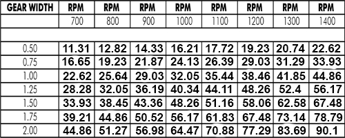
Select a gear width greater than one (1) inch from the charts keeping the speed between about 700 RPM and 1400 RPM.
For unequal flow division use the following procedure:
- Determine the outlet flow required for each leg of the hydraulic circuit.
- Use charts below to select a series and gear width for the leg with the greatest flow (keeping gear widths greater than one (1) inch).
- Move straight up the chart to select the other gear widths by choosing gear widths with the closest flow at the same RPM.
- Check the actual flow for each section to determine if acceptable using the following formula.
GEAR WIDTH / (TOTAL GEAR WIDTH) X TOTAL
FLOW FLOW FOR SECTION - If the flows are not acceptable, repeat from step (2) by choosing a different gear width or moving to a chart in another series.
FD3000 / 3100 Flow Chart
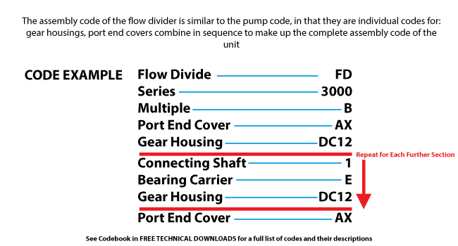
Flow Divider Assembly Coding Example
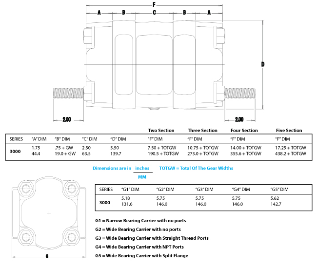
FD3000 / 3100 Dimensions
Optimal Precision and Versatility
Engineered for high accuracy, the FD3000 3100 Series boasts an output error of just 1.5% per section, delivering dependable performance where precise flow division is crucial. With modular construction and versatile section options, it adapts seamlessly to both new setups and existing hydraulic circuits requiring exact flow management.
Rugged Design, Reliable Operation
Constructed with a heavy-duty cast iron body and resilient steel gears, the FD3000 3100 Series is built to handle harsh environments and intensive operation. A corrosion-resistant paint finish enhances longevity, while high-quality seals and robust port sizes (1/2"-1") minimize leaks and deliver steady performance under pressures up to 210 bar.
Easy Integration and Control
Featuring standard mounting holes and threaded ports, installation of these dividers is hassle-free. Their compatibility with both manual and automated control systems makes them suitable for a wide range of hydraulic applications, from industrial machinery to advanced circuit designs. Compact, low-noise operation further streamlines application integration.
FAQ's of Gear Flow Dividers FD3000 3100 Series:
Q: How do I install the FD3000 3100 Series Gear Flow Dividers?
A: The FD3000 3100 Series is designed with standard mounting holes and threaded hydraulic ports for straightforward installation. Simply secure the unit using compatible mounting hardware and connect the inlet and outlet ports according to your hydraulic circuit's requirements.Q: What applications are suitable for these flow dividers?
A: These gear flow dividers are ideal for hydraulic circuits where accurate flow division or combining is necessary. They're commonly used in industrial machinery, mobile equipment, and systems demanding synchronization of multiple actuators or balanced flow distribution.Q: When should I choose a 2, 3, or 4-section model?
A: Select the number of sections based on the number of flow paths or circuits you need to divide or combine. A 2-section divider suits dual-circuit systems, while 3- and 4-section variants are chosen for more complex circuits requiring multiple synchronized outputs.Q: Where can these flow dividers be used with respect to environment and temperature?
A: With an operational temperature range of -20C to +80C and corrosion-resistant finish, these units perform reliably both outdoors and indoors, even in challenging industrial or mobile environments where temperature fluctuations and exposure are common.Q: What process ensures the divider's accuracy in flow?
A: The FD3000 3100 Series utilizes precisely machined parallel steel gears within a cast iron body, delivering dependable, accurate flow division to within 1.5% per section. This ensures each circuit receives nearly identical flow rates as per design.Q: What are the main benefits of using the FD3000 3100 Series?
A: Key benefits include highly accurate flow division, robust construction for high-pressure applications, easy installation, modularity, low noise, and compatibility with both manual and automated controls-making them versatile solutions for demanding hydraulic systems.Q: How should the units be maintained for optimal performance?
A: Periodic inspection of seals, connections, and mounting bolts is advised. Ensure the use of clean hydraulic oil and monitor for unusual noise or leakage. The corrosion-resistant finish minimizes maintenance needs, but prompt attention to wear ensures long-term reliability.
Tell us about your requirement

Price:
Quantity
Select Unit
- 50
- 100
- 200
- 250
- 500
- 1000+
Additional detail
Mobile number
Email

More Products in Gear Flow Divider Category
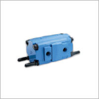
Gear Flow Dividers FD5000 5100 Series
Price 69000.00 INR / Piece
Minimum Order Quantity : 1 Piece
Pressure : High Pressure
Flow Rate : 20900 LPM
Power : Hydraulic
Structure : Other
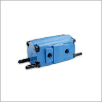
Gear Flow Dividers FD7500 7600 Series
Price 69000.00 INR / Piece
Minimum Order Quantity : 1 Piece
Pressure : High Pressure
Flow Rate : 20900 LPM
Power : Hydraulic
Structure : Other
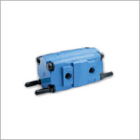

 Send Inquiry
Our Products
- Vane Pumps
- Piston Pumps
- Veljan Vane Motors
- Veljan Hydraulic Seat Valve
- Veljan Direction Control Valves
- Hydraulic Gear Pumps & Motors
- Veljan Check Valves
- Veljan Flow Control Valves
- Veljan Pressure Control Valves
- High Pressure Gear Motor
- Roller Bearing Gear Motor
- Gear Flow Divider
- High Pressure Gear Pump
- Roller Bearing Gear Pump
- Vane Pump Cartridge Kits
- Diverter Valves
- Pressure Control Valves
- Flow Control Valves
- Hydraulic Motors Accessories
- Hydraulic Pumps
- Hydraulic Seat Valves
- Mobile Sectional Valves

MZ-3, Bansi Trade Centre, 581/5, M. G. Road, Indore - 452001, Madhya Pradesh, India

Mr Pankaj Goyal
(Proprietor)
Mobile :08045803488
 Send Inquiry
 Send SMS
Developed and Managed by Infocom Network Private Limited.


